
Section inside SMPS and Block Diagram
Section inside the SMPS
1-Main filter and rectifier Section
2-Start up Section
3-Switching Section
4-Driver and Control section
5-PG (Power Good) Section
6-Output Section
 |
| Block Diagram of SMPS |
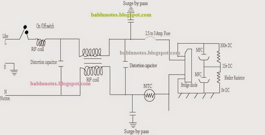
Main filter and rectifier Section:
Identification:
In this
section has Fuse, Distortion capacitor, Surge by pass Capacitor, RF Coil ,
Bridge Rectifier, and MFC (Main Filter Capacitor)
Function: It receive 230v AC and Convert into
DC 300v and Provide to Start –up and Switching Section.
Isolation (Find out this section
Working or Not):
If 300 v DC
Present on MFC, It means OK. If 300 V DC is not present, it means this section
not working.
Troubleshooting:
Problem 1. 300 v
dc is not present at MFC
Solution: In This Condition check Fuse , RF Coil Thermistor
and B/R.
Problem 2. Less
Voltage present at MFC.
Solution: In this
Condition only Check Bridge Rectifier and MFC.
Problem 3. Fuse
again and again faulty.
Solution: Check
only RF coil , Decoration Cap. And B/R, MFC. It may Any one component Short .
NOTE:
IF YOU CONNECT BULB
(60w) ON PLACE OF FUSE
1- If Bulb Glow and Off ( Charge and
Discharge): Its mean this section Working
2- If Bulb Not Glow : Check only RF coil Thermistor and switch if use in CKT.
3- If Bulb Continue Glow: : Check only RF
coil , Decoration Cap. And B/R, MFC. It may Any one component Short.


Post a Comment